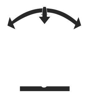
Probe Calibration
Calibrating a Surgical Drill Bit using Physical-to-Image (3D-2D) Transformation
Acknowledgements
This project was done in association with the Medical Image Guidance (MIG) team at the Indian Institute of Technology - Madras under the supervision of my principal investigator Dr. Ramya Balachandran, her PhD student Ms. Ruchitha Manne, and her Junior Research Fellow Mr. Swaminathan. This work was funded by the Department of Biotechnology (Government of India under the Ramalingaswami Fellowship Grant) and the Science and Engineering Research Board (Government of India under the Early Career Research Award).
Objective
To calibrate a surgical drill bit (probe tip) using 3D-2D transformation to find the rotation matrix \(R\) and translation vector \(t\).
Method
In order to calibrate a probe tip, there are two ways to do it.
- When the tip remains stationary in a time interval \(t_1\) to \(t_n\).
- When the tip moves around from time interval \(t_1\) to \(t_n\).
Calibration of stationary probe tip

To find the pose components, i.e., rotation \(R\) and translation \(t\), of a stationary probe tip, we can use the standard equation for displacing a point using \(R\) and \(t\): \begin{equation} \mathbf{x}’ = R . \mathbf{x} + \mathbf{t}\nonumber \end{equation} where \(\mathbf{x}'\) is the new location of the probe tip \(\mathbf{x}\) after it is rotated and translated by \(R\) and \(t\) respectively. We note that \(\mathbf{x}' = \mathbf{x}\), if the probe tip remains stationary. For time interval \([1,n]\), we can construct a system of equations as follows.
$$\mathbf{x} = R_1 . \mathbf{x} + \mathbf{t}_1$$ $$\mathbf{x} = R_2 . \mathbf{x} + \mathbf{t}_2$$ $$\vdots$$ $$\mathbf{x} = R_n . \mathbf{x} + \mathbf{t}_n$$
We can write the first equation like,
$$R_1 . \mathbf{x} + \mathbf{t}_1 = R_2 . \mathbf{x} + \mathbf{t}_2$$ $$R_1 . \mathbf{x} - R_2 . \mathbf{x} = \mathbf{t}_2 - \mathbf{t}_1$$
Repeating this LHS and RHS obtained from entire time interval \([1,n]\), we can construct a matrix formulation as follows,
\begin{equation} \begin{pmatrix} R_1 & -R_{2}\newline R_1 & -R_{2}\newline \vdots & \vdots\newline R_n & -R_{n-1} \end{pmatrix} t = \begin{pmatrix} t_2 & -t_1\newline t_3 & -t_1\newline \vdots & \vdots\newline t_{n-1} & -t_n\newline \end{pmatrix}\nonumber \end{equation}
which takes the form,
$$A t = b$$
However, the matrix \(A\) is non-square, i.e., it is of size \(n \times 2\). Therefore, we use the Moore-Penrose pseudoinverse to find \(t\) as follows,
$$t = {(A^T A)}^{-1} A^T b$$
Calibration of moving probe tip
To find the pose components, i.e., rotation R and translation t, of a moving probe tip, we perform point-based rigid registration as follows.
- Compute weighted centroid \(\bar{x}\) and \(\bar{y}\) using points \(\langle\)\(\bar{x}\)\(_i\) , \(\bar{y}\)\(_i \rangle\).
- Compute the displacement of each point using,
$$\mathbf{\tilde{x}}_i = \mathbf{x}_i - \bar{\mathbf{x}}$$ $$\mathbf{\tilde{y}}_i = \mathbf{y}_i - \bar{\mathbf{y}}$$
- Compute the covariance matrix using,
$$H = \ \sum_{i}^{N} \mathbf{\tilde{x}}_i \mathbf{\tilde{y}}_i^t \ $$
- Perform Singular Value Decomposition of H.
$$H = U \Lambda V $$
- Obtain the rotation matrix.
$$ R = V . diag(1, 1, det(VU)) . U^t$$
- Obtain the translation vector.
$$ \mathbf{t} = \mathbf{\bar{y}} - R\mathbf{\bar{x}} $$